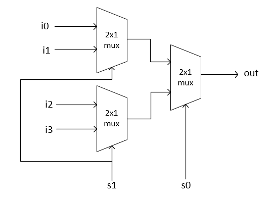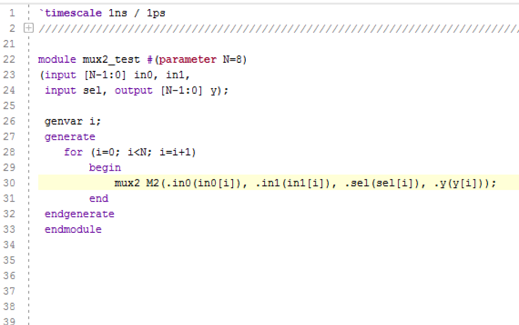


The hardware schematic for a 2:1 multiplexer in dataflow level modeling is shown below. This operator ? means that the output Y becomes equal to data D1 if select line S is true otherwise D0 is the final output. I have used a ternary operator for the output Y. Now since this the dataflow style, one is supposed to use assign statements. There’s no need for data- type declaration in this modeling. To start with this, first, you need to declare the module.
MUX 4X1 VERILOG PROGRAMME BY USING 2X1 TEST BENCH CODE
Verilog code for 2:1 MUX using data flow modeling Where Y is the final output, D0, D1, and S are inputs. For coding in the dataflow style, we only need to know about the logical expression of the circuit. It describes the combinational circuit by their functions rather than their gate structures. The dataflow level shows the nature of the flow of data in continuous assignment statements ( assign keyword). RTL schematic Gate level modeling Data flow modeling

It is the hardware implementation of a system. This is the design abstraction, which shows the internal circuitry involved. Here’s the final code of the 2:1 mux using gate-level modeling. The endmodule marks the end of the module. Similarly for and gate, T1, D1, and T2, D2 are inputs to two and gates and S and Sbar are their respective output. and not and or are the predefined built-in gates, and we’re instantiating these gates with their respective input-output ports.įor example for not gate, Sbar is the output and S is the input. Next comes the instantiation part for gates. But in the gate- level, we only declare the intermediate variables as wire there’s no need for reg or wire declaration for input-output entities. You might have noticed that other modeling styles include the declaration of variables along-with their respective data- types. Next comes the declaration of input, output, and intermediate signals. Note that we don’t declare intermediate signals while defining the module. Y is the output and D0, D1 and S being input are written after. The order of mentioning output and input variables is crucial here, the output variable is written first in the bracket, then the input ones. Verilog code for 2:1 MUX using gate-level modelingįor the gate level, we will first declare the module for 2: 1 MUX, followed by the input-output signals.


 0 kommentar(er)
